
Learning how to tune an antenna is important because a poorly tuned antenna can reflect nearly 50% of your radio’s power back into your equipment. This knowledge proves crucial for anyone who uses radio equipment – amateur radio operators, CB communicators, or professionals.
Standing Wave Ratio (SWR) measures your antenna’s efficiency. The measurement shows how well your antenna broadcasts RF energy into the air rather than bouncing it back to your transmitter. RF experts aim for an SWR below 1.5:1, while values above 2:1 reduce performance substantially. Return loss, measured in decibels (dB), works among SWR to show power returning to your radio instead of transmission. A perfect system shows infinite return loss because nothing reflects back.
Radio enthusiasts face poor signal quality, interference problems, or equipment damage due to improper antenna tuning. High SWR levels damage solid-state transmitters, though tube transmitters prove more forgiving. Standing waves on your coaxial cable create “RF in the shack” issues as SWR rises and disrupt other electronic devices.
This piece breaks down antenna tuning basics. You’ll learn about resonant frequency, impedance, and radiation patterns in clear terms. The knowledge helps you optimize your radio system’s performance, whether you’re a first-time setup or fixing an existing antenna.
Understanding SWR and Return Loss in Simple Terms
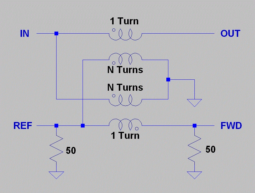
Image Source: VK8RH Amateur Radio Projects
Radio signals bounce back from your antenna instead of radiating into the air, and this creates standing waves. Your transmission line and antenna’s impedance mismatches cause this reflection. You’ll achieve the best antenna tuning performance by understanding these concepts.
What is SWR and how it affects signal transmission
SWR (Standing Wave Ratio) tells you how well radio frequency energy flows from your transmitter through the transmission line to your antenna. The ratio shows the maximum and minimum voltages along a transmission line. This measurement reveals how well your antenna’s impedance matches your transmission line’s impedance.
The SWR scale begins at 1:1, which means a perfect match without reflections, and extends to infinity for complete reflection. Mismatched impedances force some transmitted power back toward your radio. This creates standing waves that demonstrate voltage and current peaks and valleys along your cable.
Let’s look at what different SWR readings mean:
- SWR 1:1: Perfect match, 100% of power transmitted (ideal but rare)
- SWR 1.5:1: Excellent in practice with minimal reflection
- SWR 2:1: Marginally acceptable with about 11% power reflected
- SWR 3:1: Poor match that reflects 25% of power
Equipment stress and wasted transmitter power increase with higher SWR values. A transmitter pushing 10,000 watts with 1.05:1 VSWR creates 725 volts RMS maximum in your transmission line. The same line experiences 2,236 volts RMS at 10:1 SWR. This voltage surge can harm components and reduce system reliability.
Return loss as a measure of reflected power
Return loss gives us another perspective on signal reflection measured in decibels (dB). This measurement compares returned power to transmitted power. Better performance comes with higher numbers that indicate less reflection.
You can calculate return loss with this formula: Return Loss (dB) = -20 × log10|Γ| where Γ represents the reflection coefficient. Here’s what different return loss values mean for power reflection:
- Return loss of 20 dB: Only 1% of signal power reflected (excellent)
- Return loss of 15 dB: About 3% power reflected (very good)
- Return loss of 10 dB: Approximately 10% power reflected (acceptable)
- Return loss of 6 dB: About 25% power reflected (poor)
Engineers prefer return loss over SWR because logarithmic displays make it easier to compare small and large numbers on the same scale.
Why low SWR and high return loss are desirable
Your antenna system works efficiently with low SWR and high return loss values. Here’s why these measurements matter:
Your antenna radiates nearly 97% of total energy when return loss exceeds 15 dB (VSWR less than 1.43). Poor matching wastes power, shrinks transmission range, and creates inefficient operation.
Reflected power stresses your transmission lines and radio equipment. These reflections generate voltage and current peaks that might damage sensitive components, especially in solid-state transmitters.
Better matching improves signal quality. Reflected signals can mix with your primary signal and create phase shifts and delays. These issues reduce audio quality in receivers. Digital communications need precise timing and signal integrity.
Transmission line losses grow at higher frequencies, which makes good SWR more crucial.
RF systems need a minimum return loss of 15 dB (VSWR under 1.43:1). Critical applications benefit from return loss above 20 dB, though values beyond 10 dB give diminishing practical benefits in most standard communication systems.
How to Measure SWR and Return Loss

Image Source: Allelco
The success of antenna tuning depends on accurate measurements. You need the right tools and techniques to measure SWR and return loss. Without them, antenna system optimization becomes pure guesswork. The simple SWR meter is usually the first tool an operator acquires when learning how to tune an antenna.
Using an SWR meter: single vs dual needle
SWR meters come in two main designs. Each design gives you different advantages for measuring signal reflection.

Single-needle meters like the Fumei RS-40 shown here need manual calibration before each measurement. The user sets the meter to “calibration” or “forward” position and transmits a signal. Next, they adjust the calibration knob until the needle matches the calibration mark. The meter then switches to “SWR” or “reflected” position to get the actual reading. Many radio operators like single-needle models because they allow exact manual calibration. This process requires specific steps for each measurement.

Cross-needle (dual-needle) meters like the Daiwa CN-501H shown above, show both forward and reflected power at the same time with two separate needles. The point where these needles cross shows the SWR value without any calibration. This setup gives you three measurements at once: forward power, reflected power, and SWR. Dual-needle meters help you make quick assessments and dynamic adjustments easily.
Connecting the meter between radio and antenna
The right connection setup ensures accurate SWR measurement. The meter must sit between the transmitter and antenna system.
The correct setup requires:
- Connect the antenna cable to the “ANT” or “ANTENNA” port on the SWR meter.
- Connect the transmitter to the “TX,” “XMIT,” or “TRANSMITTER” port with a short patch cable.
- Check all connections before taking measurements.
People often make mistakes by reversing these connections. The labels sometimes appear on the meter’s front panel instead of the connectors. This requires careful attention.
Systems with an antenna tuner follow this sequence: radio → SWR meter → antenna tuner → antenna. This setup lets you monitor true SWR values before the tuner matches them. The SWR displayed on radios with internal antenna tuners might show perfect matching. However, an external meter placed before the tuner reveals the actual, often higher SWR in the feedline.
Reading and interpreting SWR values
The SWR readings tell you a lot about your antenna system’s performance:
- 1.0 to 1.5: Great performance with minimal reflection. This range shows near-perfect power transfer from transmitter to antenna.
- 1.5 to 1.9: Good performance with small impedance matching issues. The system works well but could use some fine-tuning.
- 2.0 to 2.4: This range points to major issues with installation or antenna adjustment. You should fix these problems to avoid inefficiency and equipment stress.
- Above 2.5: This zone shows serious mismatch issues. Running equipment with SWR above 3.0 can damage transmitter components and wastes significant power.
The measurement location affects your readings. Transmission lines reduce the reflected wave as it travels back to the source. SWR readings are highest near the antenna and get better with distance. You’ll get the most accurate antenna performance reading by placing the meter close to the antenna feedpoint.
Measuring across multiple frequencies gives you better insights. You can learn about your antenna system’s bandwidth by comparing readings at the lowest and highest channels of your operating range.
Choosing and using an antenna tuner
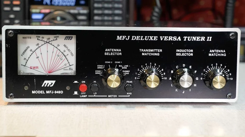
Image Source: KB9VBR Antennas
Antenna tuners are among the most misunderstood devices in amateur radio. These devices don’t actually tune your antenna—they serve a completely different purpose.
What do antenna tuners do
In stark comparison to this misleading name, antenna tuners (also called antenna matching units or transmatch) work as adjustable impedance transformers between your radio and antenna system. They accept whatever impedance the antenna presents and convert it to approximately 50 ohms—the impedance most modern transceivers need to see. This matching lets your transceiver deliver maximum power to the antenna system.
Your radio operates at full potential without activating protection circuits that would reduce power output when it sees a proper 50-ohm impedance match. High SWR conditions may trigger these “foldback” circuits and limit your transmitting capability without an antenna tuner.
Note that the tuner only changes the impedance your radio sees—it doesn’t affect the actual SWR between the tuner and antenna. Any high SWR beyond the tuner stays unchanged and may still cause power loss as heat in your feedline.
Popular antenna tuners
Two main types dominate the market:
Manual Tuners

- Feature two variable capacitors and a switchable inductor
- Need hands-on adjustment to find optimal settings
- More reliable because they need no power source
- Cost less than automatic models
- Handle wider impedance ranges in many cases
- Popular models include the Comet CAT-300 which is an excellent tuner
Automatic Tuners

- Select combinations of inductors and capacitors faster via relays
- Offer “push-button” convenience with minimal operator involvement
- Come in indoor and remote/outdoor weatherproof versions
- Keep frequency/settings in memory for quick band changes
- Leading brands include LDG, Palstar, MFJ, and ICOM, the ATU-100 V3.2 1.8-55MHz by N7DDC is popular as well
- Have limited matching range compared to some manual tuners
Built-in automatic tuners come with most modern transceivers. These are designed to make minor impedance corrections—typically handling SWR up to only 3:1. External tuners become vital for bigger mismatches or non-resonant antennas like random wires.
Using an antenna tuner
Manual tuners require this simple procedure:
- Turn your transmitter power down to its lowest setting to protect components
- Select your desired operating frequency
- Set your radio to a constant carrier mode like CW or AM
- Adjust the inductor dial until you hear maximum noise (without transmitting)
- Transmit at low power and adjust capacitors to achieve minimum SWR
- Note the settings for future reference
Automatic tuners need just a press of the “tune” button while transmitting at reduced power. The tuner cycles through various combinations until it finds the optimal match, usually within seconds.
You should know that antenna tuners help your radio operate more efficiently with imperfect antennas, but they don’t improve the antenna’s actual radiation characteristics. Using properly resonant antennas remains the best approach whenever possible.
Step-by-Step Antenna Tuning Process

Image Source: Moonraker
Proper antenna tuning changes a mediocre radio setup into an exceptional one. You need patience, precision, and proper technique to achieve the best performance.
Tuning mobile antennas in-place on vehicles
Your mobile antennas must be tuned while mounted on the vehicle they’ll be used with. Similar vehicles can produce different results because of slight variations in body construction and mounting location. First, park your vehicle far from buildings, light posts, and metallic objects that could affect readings. Take measurements with all doors and hatches closed to ensure consistent results.
To tune a mobile antenna:
- Cut the antenna slightly longer than needed—you can always remove material but adding it back is impossible
- Connect your analyzer between the radio and antenna
- Sweep frequencies wider than your operating range to see the performance curve
- Check if adjustments are needed based on SWR readings:
- If SWR on high-frequency channels (like channel 22) exceeds low-frequency channels (like channel 1), your antenna is too long
- If SWR on low-frequency channels exceeds high-frequency channels, your antenna is too short
- For lengthy antennas, trim in small increments (1/8″ to 1/4″) until you reach optimal SWR
Adjusting portable antennas in open environments
Portable antennas need tuning “in the clear” to simulate real-life conditions. Mount them on non-conductive supports with plenty of free space around them. You can also suspend them from non-conductive cord at their typical operating height.
For directional antennas like Yagis:
- Start with the antenna aimed in one direction
- Transmit and wait 60 seconds to record signal readings
- Rotate the antenna 45 degrees (matching compass points: N, NE, E, etc.)
- Wait another 60 seconds and record new readings
- Keep going until you complete a full 360° rotation
Choose the direction that gives you the strongest readings across your desired frequencies.
Equalizing SWR at band edges for resonance
The main goal of antenna tuning is making it usable across its designed frequency range. You want equal SWR readings at both ends of your frequency band instead of focusing only on the lowest possible reading.
For dipole antennas:
- Pick your target frequency for resonance tuning
- Calculate estimated length using the formula: 234/frequency (MHz)
- Measure SWR at both band edges
- If readings differ by a lot, adjust antenna length:
- Shorten both elements equally to raise resonant frequency
- Lengthen both elements equally to lower resonant frequency
Small adjustments often lead to big improvements. Precision is key—moving an antenna a few inches or changing length by 1/4″ can transform its performance completely.
Adjusting for Impedance, Reactance, and Resonance
Proper impedance matching is the foundation of antenna tuning that bridges theoretical physics and practical radio operation.
Identifying if the antenna is too long or too short
The SWR curve across frequencies tells us if an antenna needs lengthening or shortening. This relationship shows clear patterns:
- SWR readings lower than your target band mean your antenna is too long
- SWR readings higher than your target band indicate your antenna is too short
To name just one example, a mobile CB antenna might show SWR of 1.3 on channel 1 (26.965 MHz) and 2.5 on channel 40 (27.405 MHz). This means the antenna needs shortening to raise its resonant frequency. You should trim small amounts at a time—usually 1/8 to 1/4 inch—until the readings balance across your operating range.
Understanding impedance mismatch and reactance
An antenna’s impedance has two parts: resistance and reactance. The resistance shows power that radiates or becomes heat, while reactance shows energy stored in electromagnetic fields around the antenna.
A resonant antenna’s impedance becomes purely resistive (about 73 ohms for a dipole in free space), and reactance drops to zero. The antenna develops reactance off resonance—either inductive (positive) when it’s too long, or capacitive (negative) when it’s too short.
Reactance creates impedance mismatch that causes reflected power. The transmitter impedance (usually 50 ohms) should match the antenna system’s impedance to transfer power effectively. High impedance mismatches can damage your equipment. A transmitter pushing 10,000 watts into an SWR of 10:1 would see voltage peaks above 2,200 volts.
Resonant frequency and its role in tuning
Resonant frequency happens right where inductive and capacitive reactances cancel out. The antenna appears purely resistive to the transmitter at this point.
Physical dimensions determine antenna resonance. Larger antenna elements create lower resonant frequency. You can tune precisely by adjusting length:
- Shorter antennas have higher resonant frequency
- Longer antennas have lower resonant frequency
- The formula 234/frequency(MHz) gives you a starting length for dipoles
A resonant antenna doesn’t always show exactly 50 ohms impedance. A resonant dipole’s feedpoint resistance is about 73 ohms, which creates a small mismatch (SWR = 1.5) even at perfect resonance.
Fixing Common Mode Currents and Feedline Issues
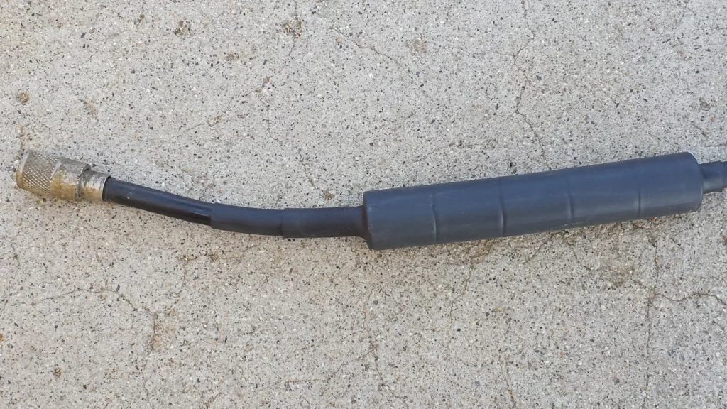
Image Source: Palomar Engineers
Common mode currents work as a hidden enemy in your antenna tuning efforts. Your system’s performance can suffer by a lot even with perfect SWR readings when these unwanted currents flow on your coaxial cable shield’s outside.
Detecting common mode currents via SWR changes
You can spot common mode currents through erratic SWR behavior. Your SWR readings will change as you move or touch the feedline – this is a clear sign. These currents are likely causing trouble if your antenna’s SWR changes with different coax lengths without other modifications.
Watch out for these signs:
- RF interference with household electronics
- Disrupted antenna radiation patterns
- Higher noise levels during reception
- RF “burns” when touching metal components near your radio
You can run a simple test. Check your analyzer while moving your hand along the coax—any reading fluctuations show current on the shield’s exterior.
Using baluns for balanced antennas

Baluns (balanced-to-unbalanced transformers) stop feedline radiation by blocking common mode currents. Current baluns work better than voltage baluns for most antenna systems.
Your antenna system stays isolated because current baluns add impedance to unwanted common-mode paths. This isolation prevents the coaxial shield from becoming an unplanned radiating element of your antenna.
Pick your balun based on your antenna type:
- For dipoles and other balanced antennas: 1:1 current balun at the feedpoint
- For raised vertical antennas: feedline current choke positioned under the radials
Building simple common mode chokes (Ugly Baluns)
 The “ugly balun” stands out as the simplest common mode choke. It’s just coiled coaxial cable that creates inductive choking against unwanted currents.
Here’s how to build an effective air choke:
- Use 18-21 feet of coax to cover 3.5-30MHz
- Wind it in a single layer around a 3-5 inch non-conductive form
- Secure the first and last turns to the form with nylon ties
- Keep the first and last turns separate
The choke’s location matters a lot. Put it as close as you can to the antenna feedpoint to stop feedline radiation. Stubborn issues might need a second choke about 1/8 wavelength down the line for extra suppression.
Tuning Different Antenna Types
Different antenna designs need their own special tuning methods. The way adjustments affect performance depends on each antenna’s physical structure.
Whips, dipoles, loops, and J-poles
You need to adjust the length of whip antennas to achieve resonance. For mobile installations, the vehicle’s body creates capacitive effects that affect tuning. The whip’s length determines its electrical characteristics – shorter lengths raise frequency while longer lengths lower it.
A simple formula helps with dipole antennas: divide 468 by frequency(MHz) to get the total length in feet. Both elements usually need equal adjustments. You should cut dipoles a bit longer than calculated because removing wire is easier than adding more.
J-pole antennas let you tune through element length and feed point positioning. The main adjustment works with the 1/4 wave matching stub – shorter stubs raise resonant frequency while longer ones lower it. The feed point position needs adjustment along both radiator and stub to get the best SWR.
Multi-band antennas and section-wise tuning
Multi-band antenna tuning needs a step-by-step approach. Always start with the highest frequency band and work your way down. This order matters because higher band adjustments affect lower bands.
The process for trap-type vertical antennas:
- Start by adjusting the trap housing for the highest band
- Make very small movements as frequency changes faster
- Check all previous adjustments after each band is optimized
Multi-band antennas use tuning networks with multiple adjustment points. These points interact with each other, making them harder to tune than single-band antennas.
Gamma, Y, and T match adjustments
Gamma matching systems do three things: they transform impedance, compensate inductively, and convert balanced-to-unbalanced signals. You need to coordinate three things when adjusting a gamma match: rod length, rod spacing, and gamma capacitor.
T-matches work as shunt-matching techniques for dipoles or Yagi antennas’ driven elements. Y-matches provide similar functions with different physical layouts. These matching systems help transform impedance precisely between the antenna’s natural impedance and the feedline impedance you want.
The antenna should be in its final position during tuning because nearby objects affect impedance characteristics by a lot. You’ll need to switch between adjustments until you get the lowest SWR.
Conclusion: How to tune an antenna
Antenna tuning is the life-blood of effective radio communication. This piece explored how SWR and return loss indicate your antenna system’s performance. These measurements show if radio energy radiates into the air or reflects back to your equipment.
You need to understand a few basic concepts to get optimal antenna performance. Your antenna resonates when inductive and capacitive reactances cancel each other out and create a purely resistive load. Good impedance matching maximizes power transfer between your radio and antenna system. The suppression of common mode currents prevents unwanted radiation from feedlines.
Radio operators should know that different antenna types need specific tuning approaches. Whips, dipoles, loops, and multi-band antennas come with their own challenges. The tuning process follows similar principles whatever the design. You measure performance, make precise adjustments, and verify improvements across your operating band.
Antenna tuners are practical solutions for impedance mismatches but can’t improve an antenna’s basic radiation characteristics. A properly designed and installed antenna is vital before you try matching devices.
Antenna tuning blends science with art. The process needs patience, precision, and systematic testing. Perfect 1:1 SWR might be hard to achieve in real-life conditions. Even small improvements can dramatically boost your communication range, signal clarity, and equipment life. Radio enthusiasts who become skilled at these techniques will discover their system’s full potential and avoid common amateur setup problems.